
EFIS 2
818. August 2014 by Peter
A few months ago I made my second EFIS for the cockpit. The main reason is not “Because there are two in a cockpit” but because the one I already use not is all that stabile.
It / EFIS1 was one of the first units I builded. It uses the Hispapanel printed circuit board. But somehow – and probably because it is one of my fIrst builds – it has never worked flawless. Some of the switches do not work unless you wriggle them a bit, the backlighting never seemed to work and the rotary switches are pretty hard to turn. And latest I switched to a new MasterCard and is unable to get any signal from the unit.
So I decided I better make the second EFIS (I have had the panel laying around for more than half a year) and swap them so the newly build will be the primary.
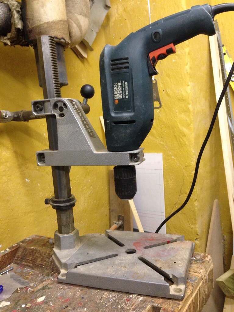
Use a drill press
The tricky part about the EFIS is that you must build dual knobs. The way to achieve this is to drill out the shaft of a rotary switch. When you know how to it is not that hard, but it requires the right tool. I have no idea what this tool is called – neither in Danish or English. But it is a stand for a drill that ensures you drill vertical. EDIT: Thanks to Ians comment: It is a drill press. 🙂
Here is how to do it:
- You must take the rotary switch apart. Make sure to do it inside a plastic bag. Inside the rotary switch there is a spring and two small balls. They pop out when you open the switch. You do not want to loose these! Hence the “Inside a bag”.
 Take the shaft/base and cut the shaft off.
- On the button of the base there (normally) is a hole about 3 mm wide. Use the vertical drill and drill your way through using a 3mm drill.
Next switch to a 6mm drill and expand the (3mm) hold you just made to 6mm.
The reason for this two-step maneuver is to ensure the hold is right in the middle of the base. The 3mm drill in the 3mm hole helps. - Cut a piece (like 10-15 cm) of a 6mm brass/aluminium/steel-tube. It must be a tube as the second shaft will run inside the tube.
- Put the tube through the hole you just made.
The tube should stick 3 mm out on thebuttom of the base. No more – no less. - The tube should sit tight on the base. You should not be able to turn the tube without the base turning.
Should this however (most likely) be the case then take the tube out and give it a small squeeze where the base should fit. Just a small squeeze to make it a bit oval/wider. Just remember there should still be room for the inner shaft. - Take the spring that you took out from the switch and cut it in half.
Well while you are at it, cut it in quarters. Throw the middle away.
The longer the spring the harder the resistance when you turn the knob. 4 rounds on the spring is enough for me. - Putting the spring and balls back in to place is a bit tricky. Put in the two springs you just cut and then put on the hat/top (Make sure the springs stays in place).
There is a slideway on one side of the top/hat. Insert the first ball via this slideway. When in place make sure to hold the shaft and hat together. If not the ball jumps out and is nowhere to be found.
Turn (only) the shaft 180 deg so the other side of the base is located in front of the slide way. Place the second ball (Use a small screwdriver to put it in place). - Hold the top/hat and the base tightly together. Get the white part / floor and press it in place. Make sure the 4 “fingers” grabs and locks.

Voilá you have now made a dual switch.

4 rotary switches with new shafts.
On the second switch use a 3 mm shaft. Drill a small (1,5 mm will be good) hole throughout the shaft of the second switch/encoder from one side of the shaft to the other (horizontally – opposite of what you did to the first rotary switch where you drilled vertically).
Also drill a hole through your 3mm shaft. It might be easier if you flatten the side of the shaft a bit with a file. Connect the two parts with some steel wire and perhaps some hot glue. You just must make sure it is aligned so it can torn all the way around (I am just saying: Check movement before you start gluing).
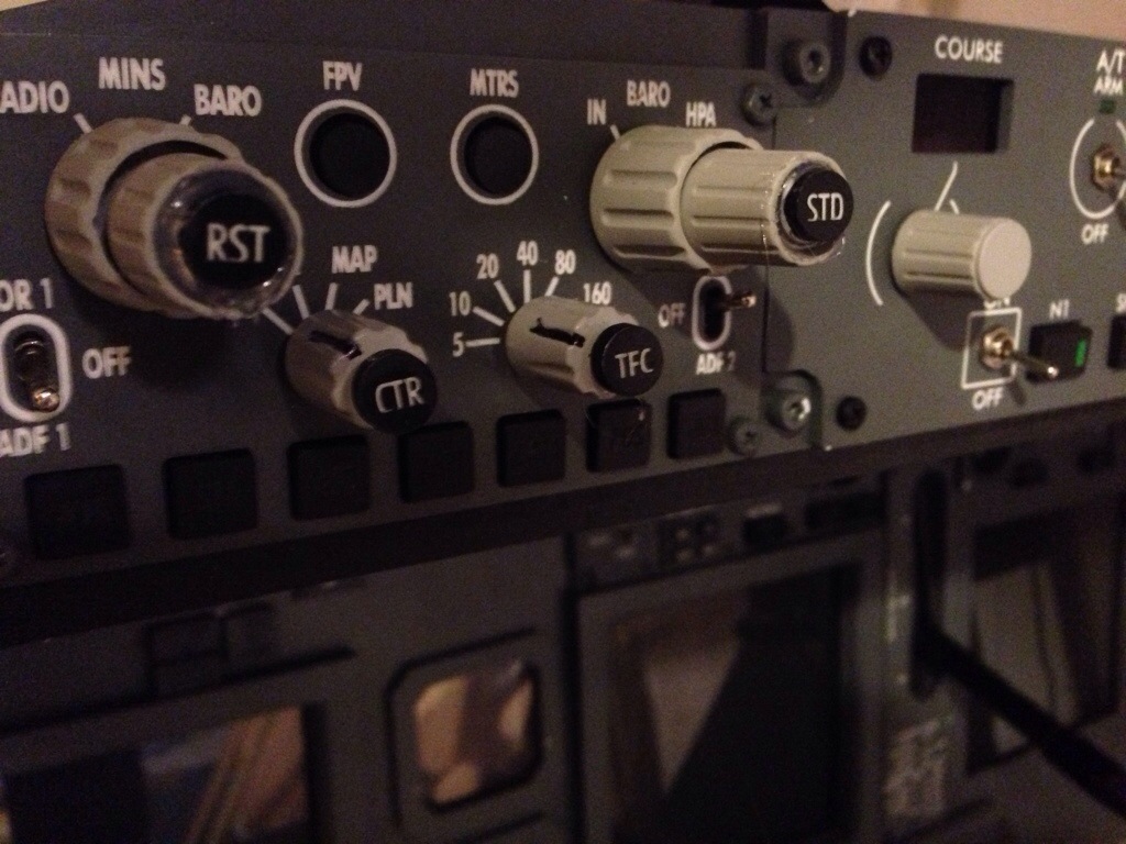
 On this picture you can see through the shaft of the minimums selector. On the picture only the 6mm shafts are installed.
My knobs are from OpenCockpits, the panels from Hispapanels. The picture below shown the final product.

Hi Peter,
Your 2nd EFIS is looking great. I have built an EFIS using Leo Bodnar boards which I hope to upgrade to dual rotaries like you have, in the near future, so you have posted a very useful post for me. Thank you for sharing your efforts.
BTW, the vertical control mechanism you have for your power drill is called a drill press. They are a cockpit builder’s best friend indeed. Good for all sorts of straight drilling so your switches don’t attach to your plexiglass at a crooked angle!
Take care and thanks again for sharing what you’ve learnt with the building community.
Cheers,
Ian.
Thanks Ian. Just updated the text. 🙂
/Peter
Great Tutorial. Will soon be looking at building FO EFIS myself.
All the best,
Ed
Hi Peter. This is a great tutorial. I am in the process of finishing up my EFIS based on panels I bought from Hispapanels and connecting to a Leo Bodnar card.
I have a question on the wiring of the rotary switch. How do I know which switches to wire? for example, the left switch is for PLAN, VOR, etc. There are 4 positions. Do I assume I need to wire terminal 1, 2, 3, 4, and GND?
Hi Steve.
I have been away for a weeks time.
But yeah it is pretty simple. You just connect the wires to GND, 1, 2, 3, 4.
Make sure you place the small pin/ring on top of the rotary switch in the four position. When you take off the bolt/nuts of the switch there is a washer with a small pin on. It goes in to different holes on the top of the rotary switch. Turn the shaft all the way counter clock-wise and place the pin in number 4. This way you only get 4 positions on your switch.
Install the rotary and finally place the knob so it fits the panel.
Very simple.
/Peter
Hi Steve.
You’re doing very well! Sorry about my bad English. I also build a PMDG B737 simulator with FSX. My question is, how to progaming the IFES panel TFC scale butons 5, 10, 20 …640? I I also use a rotary switch for all of you, And the Linda program. I thank you for your help too!
/Tibor from Hungary
Hi Tibor. I am not able to help with PMDG as I never have used it. /Peter
Hi Tibor.
I still haven’t gotten the ND Range (5, 10, 20, etc) to work in Linda. Their script only provides increase and decrease options. I don’t want to mess with LUA and might recommend a Linda developer write a LUA script for this.
I checked the LINDA website and there’s a version for P3D v4 but it still has the same LUA scripts as FSX.
I have switched over to ProSim737 and P3D v4 so rarely use the PMDG these days.