
Flaps panel
226. May 2014 by Peter
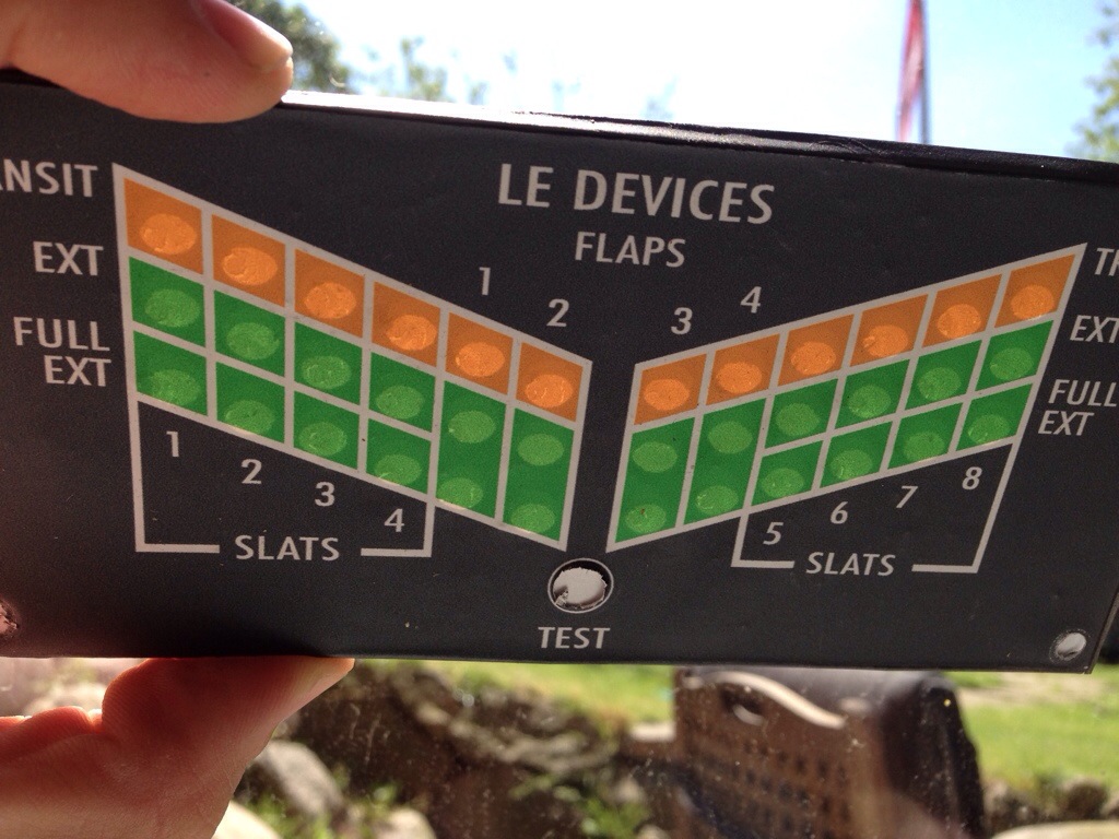
On the AFT overhead there is a panel that shows the state of the flaps.
 On the one hand it is a fairly simple panel. Just 36 LEDs. But on the other hand it takes quite many LEDs and they need to be aligned. So this is how I did it.
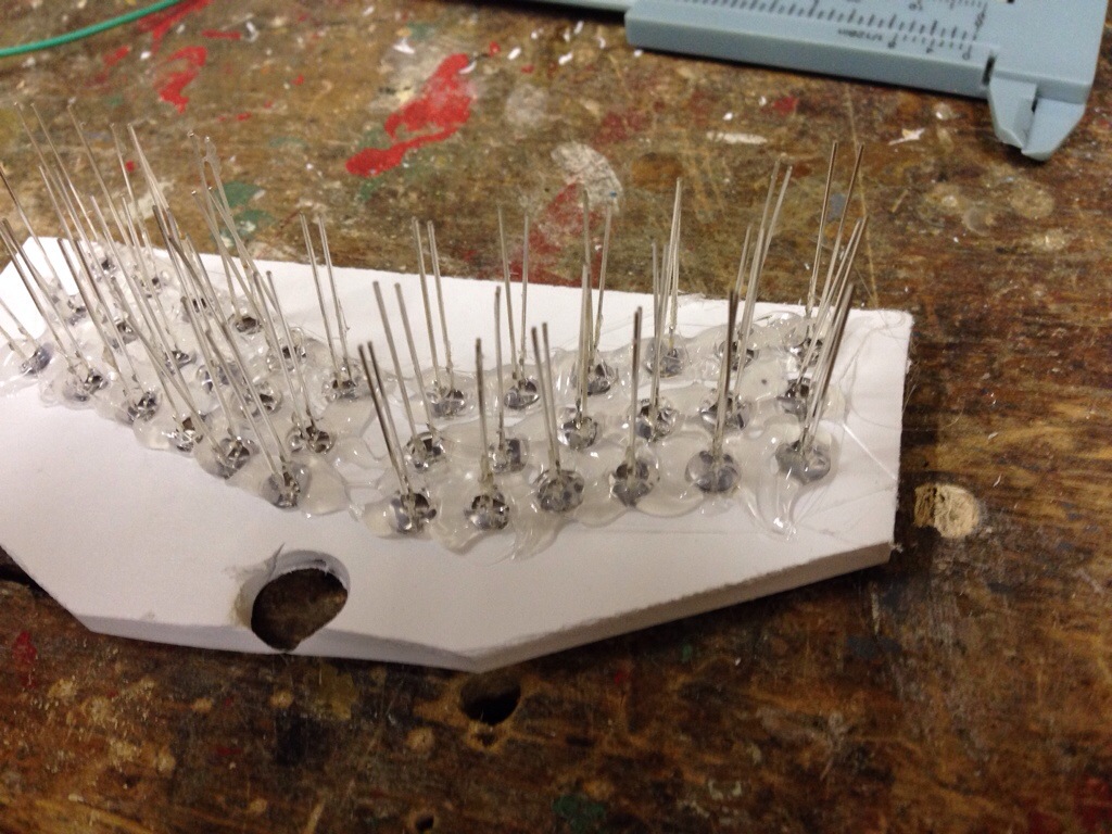
First I made two pieces of foamalux and drilled holes for the LEDs in both pieces. But as you can see from the picture the holes are not on a strait line. So I had to peel the foil off and remake them.
 The way I did was drawing a copy of the front on a piece of transparent foil and then transfer the drawing to the foam pointing a hole in the middle of each LEDs position. Using 6 mm holes for the actual panel and 5mm drill for the second piece that will hold the LEDs.
The best way to test if the holds fit the print is to hold them together and then hold it against the sun. The picture to the right was my fourth attempt to make the holes on a line.
 So after all the holes were drilled the LEDs were put in to place.
They all share GND in each section. The 6+6 yellow needs a 470 ohm LED but the green ones can be connected directly to the OpenCockpits MasterCard.
And then all you need is to wire up 38 wires and some resistors.
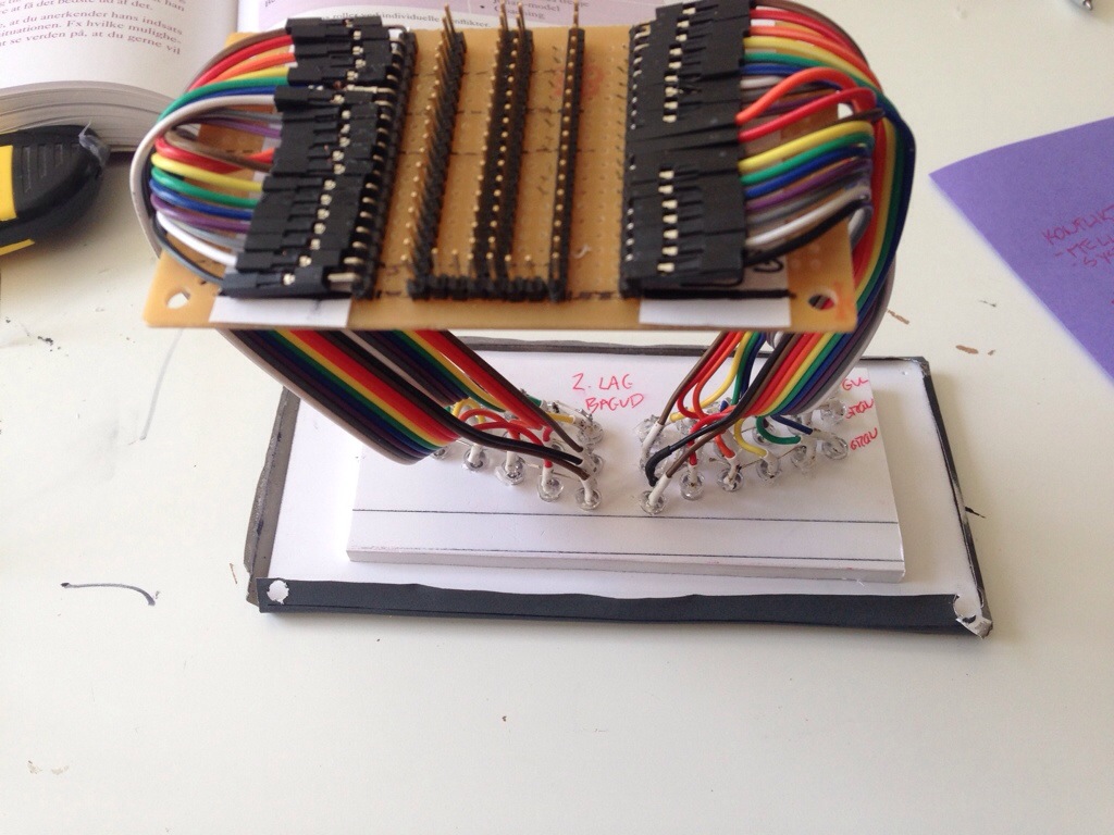 As some of you right know I really like using dupont wire. And this is another example. On the board there are two sets. One on the left side and one on the right hand side. The pins in the middle is in fact for jumpers: This panel takes up 36 LEDs/outputs on an interface card. But the left and right side moves in sync. So I thought why use 36 outputs, when I can du with 18 and then just mirror. So the two rows in the middle is for jumpers that connects the left and right side. That way I only have to connect one of the sides to the interface card to get a full working panel.


Does Prosim simulate faliures, like flaps on only one side extending?
My ACFT never fails. 😉 But yes Prosim simulates failures and can randomize failures.
But I have no idea about non-synchronous flaps extension. Can that even be simulated in FS?