
7-segments – an easier way
312. April 2013 by Peter
Some things look very complex at first but once you find the short cuts the tasks are manageable.
Guess this also goes for 7-segment displays. It is not easy – but on the other hand not in any way difficult.
First a small disclaimer. I have chosen to interface my cockpit with OpenCockpits cards. So I all ready had MasterCards and USB-expantion cards in my set-up. Other interface solutions might demand other cards or might not be as easy to work with.
Each display has 10 pins. One for each segment of the number (7) the decimal (1), A total of 8 legs. And then two GND legs. The 8 legs for the segments are shared by all units. So for a 5-digit display they share the 8 legs and just need 1 individual wire each. This reduces the number of wires from 50 to 13. The easy way to reduce the number of wires is by using a Printed Circuit Board (PCB) aimed at 7-segment displays. They virtually costs nothing compared to the time you save! Here are two examples from OpenCockpits and Hispapanels. They do the same so you can buy whichever you like. The card contains two sections for input. The 8 pin/legs in one group and one unique pin for each segment.
You also need a IO-card to control the 7-segment displays. As I use OpenCockpits cards on my cockpit the obvious choice was the OC Display card. You can run 16 units on one DisplayCard. That is equal to 1 NAV-radio (2×5) and half a COM radio (6). If you want to save a few coins you can easily solder the kit. Just make sure you buy one assembled card so you can see how to du. And remember du buy extra sockets for those ICs! This prevents you from destroying them or mounting them the wrong way.
Next step is to solder the 7-segments on to the PCB. Here it is important to remember that the 8 pins are shared. So you should build them in a way where you easily can transfer the shared connection on to the next set.

7-segment PCB with shared 8p GND connection
I my first attempt I made my own wires from hard disk cables with wafer-connectors. I can not recommend this solution! The wires easily broke off or there was no connection. The easier way is to make multiple 8-pins. Buy a set of dual-pins. And add 2×8 pins to each PCB. This way you can transfer the signal on to the next section. As shown on the picture to the right. Here you see 2×8 pins and the 5 unique pins for the display. The double-row pins of course needs to be paired on the backside.

Ready-made dupont-wire with 5 pins
On the pins my advise is to use ready-made dupont-cables with a matching header. So for the display on the picture you need wires with 8-pin heads and 5-pin heads. They can be bought in all lengths and the heads can easily be changed. So you do not have to buy cables where both length and the head matches. Just make sure you in the end have the necessary lengths and heads and then mix-to-match. Then pre-made cables has the advantage (as mentioned in this blog posting) that they work right from the start.
So to sum it up: Your layout should look like this:
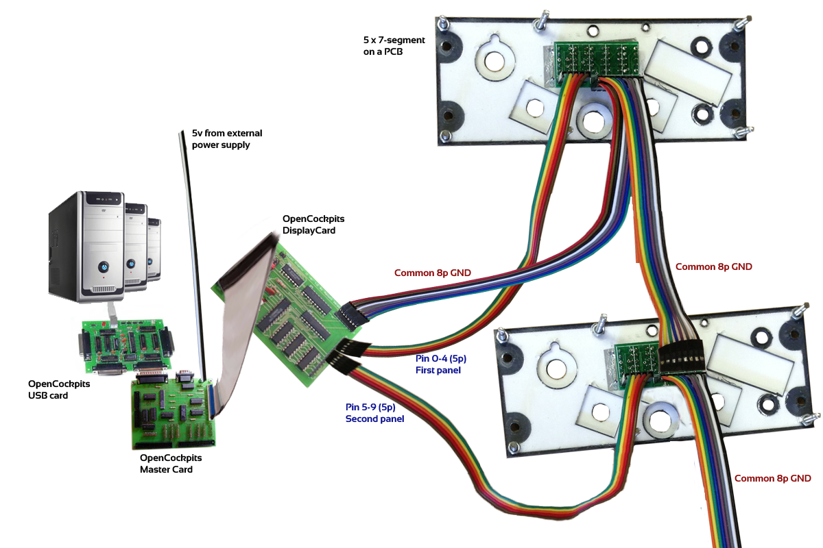
Setup
Cheers
Peter

Wow..Thanks for the writeup. I have been seriously dreading when it came time for 7-segments, but you worked it all out. Just have to make my shopping list now!
Very well explained and the pictures are a great aid, Thanks Peter for taking the time to document all this work. I’m not at this stage yet, but I will be back here when the time comes.
Peter this really is great stuff – thank you – hope you have a great time in Egypt