
OEM MIP Panel Captians side
Leave a comment12. January 2025 by Peter
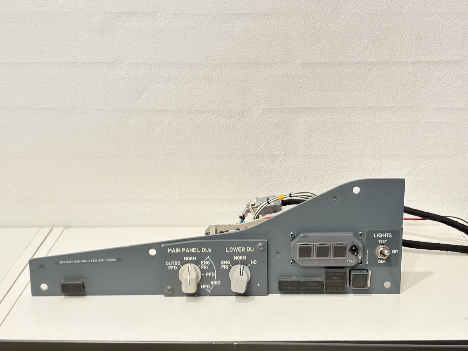
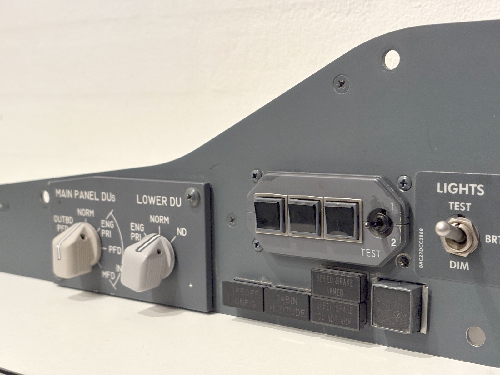
I have bought an OEM panel for the Main Instrument Panel on the captains side. Again OEM means that it is an original panel from a real aircraft. This fits perfectly with the OEM AFDS-panel that I bought a few months ago. Not I have a complete OEM panel in my cockpit!
It is actually a pretty simple panel – a few annunciators and a few switches. But it is the centerpiece of the entire cockpit when in the captain’s chair. So I am very excited about this. The panel came with lightplate for the DU-selectors, a single rotary switch (So I had to install one non-OEM), the lighttest/dim switch, 5 Korry 318 annunciators and the Korry 432 Stab Out of trim annunciator. It also has the “TakeOff Config” And “Cabin Altitude” annunciators which I am happy about.
As always interfacing an original piece of hardware in a simulator-setup requires a bit of work. The rotary switches are pretty strait forward. But be aware they are wired to both cannon-plugs on the back. So grab a multimeter and start figuring out the wiring to the cannon plugs in the back. The Light test / Dim switch caused me a bit of headache. The Korry switches / annunciators needs some work as they share some of the wiring. I am going through it in this video.
First I recommend you read the article on Korry 318’s on flaps2approach.com. It covers how to do it. But to break it down:
Korry switches are common anode. That means you need a shared positive 28v (24v can do). And the ground wire is the one that runds individually to your interface board. Luckily there are wiring diagrams on each Korry
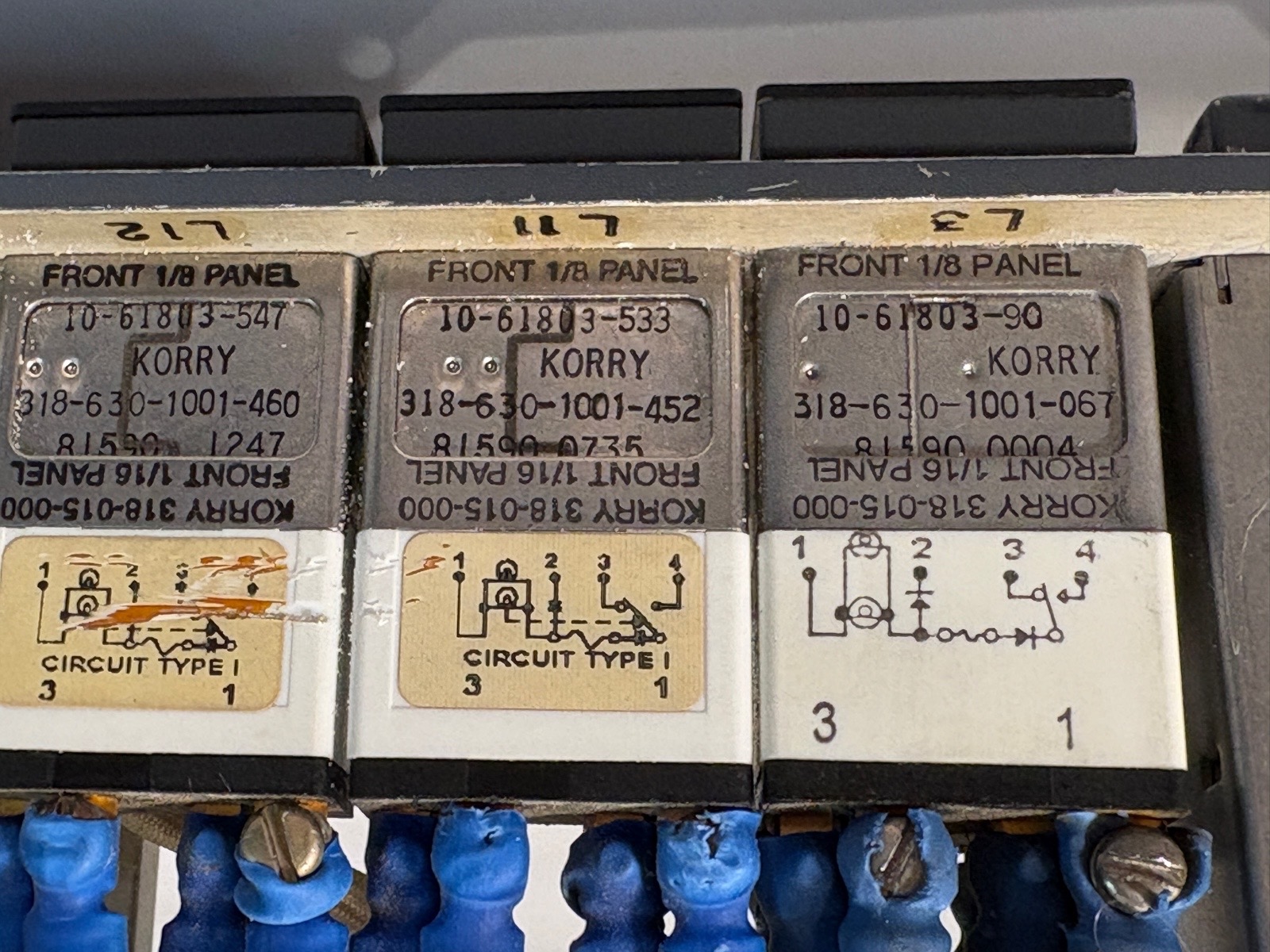
On a korry switch you also need a steady ground it order to perform the push-to-test function. The wiring of a regular Korry 318 looks like this:
Pin 1 – Steady + 28v
Pin 2 – Individual ground from Interface borad
Pin 3 – Light test – Not needed
Pin 4 – Steady Ground.
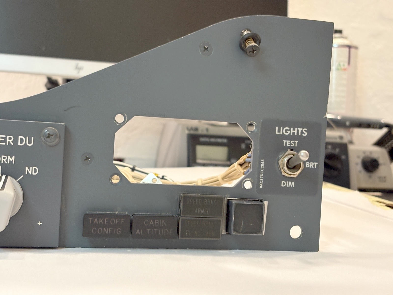
Pin 3 is hard wired light test getting a signal directly from the “Light test switch”. However in a simulator setup the light test normally is software controlled. So pin 3 must be bypassed from the Light Test switch. I ended up removing most of the wires from the light test / light dim switch and just have one set of wires going to/from the plug on the back. The “Light Dim” function is also hardware controlled and not needed in a simulator set-up – again because this is handled by the software and interface boards. A lot of the wiring was removed because it was redundant and performed functions not needed. So just to make sure there would be no conflict between hardware controlled and software controlled light tests or dimming.
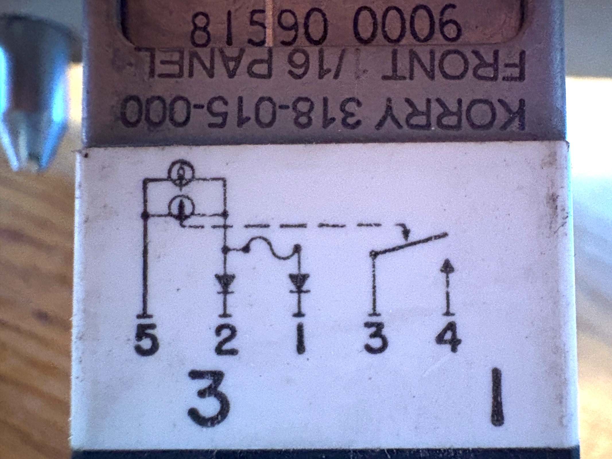
The “Below G/S” korry is a bit different that the other Korry 318 switches. It carries the same number “Korry 318” Partnumber is 318-015-000. If is different because it has 5 terminals on the back and do not have the push-to-test function. Therefore the steady GND is not needed. Pin 2 and Pin 5 is the steady +28v and the GND from your interface board. Pin 3+4 act like a switch. Pin 1 is for the hard wired light test and should not be connected.
The “Stab out of trim” Korry annunciator is a Korry 432. It is independently wired. Inside there are two sets of lightbulbs (2 on the right and 2 on the left). Each side is wired to each of the two cannon plugs on the back. There was a loose connection on my annunciator. It only worked when given a slight push. So with the help of a bit of hot glue it is now held in place.
I am not able to find matching cannon plugs (21 pin and 41 pin, female, outside bayonet) So I have extended the wiring from the cannon plugs to a set of db9 / db15 / db25 plugs. From there the wires run back to the interface boards
For interfacing I am using my CP-flight MIP board for the switches. As the annunciators are running on 28v I need another solution. So I am utilizing an extension board for pokeys called a PoExtBus16. It provides 16 outputs that can run anything from 5 to 48 volt.
Pinout
The two Cannon plugs on the back have the pinout as shown below. Pin numbers that are stroke through do not exist on the cannon plug (Empty hole). There was no rotary switch for the lower DU on my panel. So I do not know what pin does what for the lower DU
MIP /// CPT-side /// DU-panel J1
| 1 | Back light +5v | 21 | Main DU – Inbd MDF |
| 2 | Bac klight GND | 22 | Main DU GND |
| 23 | Main DU Outbd PDF | ||
| 4 | Below G/S – Pin 3 | 24 | Main DU NORM |
| 5 | Below G/S – Pin 4 | ||
| 6 | Below G/S – Pin 2 | ||
| 28 | LED: Stab Trim Left +28v | ||
| 29 | LED: Stab Trim Left GND | ||
| 34 | Light Test Bright | ||
| 15 | Lower DU | 35 | Light Test Bright GND |
| 16 | Lower DU | 36 | Light test? |
| 17 | Lower DU | 37 | Light test? |
| 18 | Lower DU | 38 | Light test? |
| 19 | Main DU Inbd Eng Pri | 39 | Light test? |
| 20 | Main DU Inbd PDF | 40 | Light Test Dim |
| 41 | Light Test Dim GND |
MIP /// CPT-side /// DU-panel J2
| 13 | Pin 2 – Cabin Alt | ||
| 14 | Korry 3 – All | ||
| 3 | +28v – Stab Trim Right | 15 | Lower DU – (Sleved) |
| 16 | Lower DU – (Sleved) | ||
| 5 | Pin 2 – SpdBrk Armed | 17 | Lower DU – (Sleved) |
| 6 | Korry 4 – All | 18 | Lower DU – (Sleved) |
| 7 | Pin 2 – SpedBrk Not Arm | 19 | Main DU Inbd Eng Pri(Sleved) |
| 8 | Pin 1 – Below G/S 1 | 20 | Main DU Inbd PDF (Sleved) |
| 9 | Korry 1: Extras | 21 | Main DU – Inbd MDF (Slev) |
| 10 | GND – Stab Trim Right | 22 | Main DU GND (Sleved) |
| 11 | Pin 1 – SpedBrk Not Arm | 23 | Main DU Outbd PDF (Slev) |
| 12 | Pin 2 – TakeOff Config | 24 | Main DU NORM (Sleved) |
Wiring the different parts are shown in this tabel
MIP /// CPT-side /// DU-panel – Annunciators
| Below G/S | 1 – GND 28v | J2 – 08 | |
| 2 – GND 28v | J1 – 06 | ||
| 3 – Switch | |||
| 4 – Switch | |||
| 5 + 28v | J2 – 09 |
| Cabin ALT | 1 + 28v | J2 – 09 | |
| 2 – GND 28v | J2 – 13 | ||
| 3 | J2 – 14 | ||
| 4 – GND 28v | J2 – 06 |
| Takeoff Config | 1 + 28v | J2 – 09 | |
| 2 – GND 28v | J2 – 12 | ||
| 3 | J2 – 14 | ||
| 4 – GND 28v | J2 – 06 |
| SpdBrk Armed | 1 + 28v | J2 – 11 | |
| 2 – GND 28v | J2 – 05 | ||
| 3 | J2 – 14 | ||
| 4 – GND 28v | J2 – 06 |
| SpdBrk Don’t arm | 1 + 28v | J2 – 11 | |
| 2 – GND 28v | J2 – 07 | ||
| 3 | J2 – 14 | ||
| 4 – GND 28v | J2 – 06 |
| Stab Trim | 1 + 28v | J2 – 03 | |
| 2 | |||
| 3 | |||
| 4 – GND 28v | J2 – 10 |
MIP /// CPT-side /// DU-panel – Switches
| Backlight | 5v | J1 – 01 |
| GND | J1 – 02 |
| Main DU | GND | J2 – 22 |
| Outbd PDF | J2 – 23 | |
| Norm | J2 – 24 | |
| Eng Pri | J2 – 19 | |
| PFD | J2 – 20 | |
| MDF | J2 – 21 |
| Lower DU * | GND | J2 – 15 |
| Eng Pri | J2 – 16 | |
| Norm | J2 – 17 | |
| ND | J2 – 18 |
- Lower DU: Own wiring. Not OEM wiring
| Light | GND | J1 – 35 + J1 – 41 |
| Test | J1 – 34 | |
| Dim | J1 – 40 |
| Below G/S | GND | J1 – 04 |
| Push | J1 – 05 |
