
Light controls
143. March 2015 by Peter
I would try to play a bit around with relays a month ago. So I bought some 5v relays. The OpenCockpits MasterCard supplies 5v outputs, right!? Well, no. It only supplies 3.5 v. So I was not able to use my 5v relays. Lesson learned.
But then I bought a 4 channel relay board from eBay costing just $4. What this board does is that it can work with just 3.3v. It also needs 5v. The OpenCockpits MasterCard supplies both.
Light controls in Prosim737
On the relay board I have connected my 12v from the power supply and from the relay board all wires for backlighting is installed. Via Prosim I have configured that the relay should flick when there is enough power on the aircraft to power the back lightning.
So there is no backlight of the cockpit until ground power orAPU/ENG BUS is on.
Such a neat feature!
And a shout out to the Prosim737-team. With Prosim all I had to do was to configure what exit on my MasterCard that should be assigned to the predefined light gates in Prosim. Very easy!

Hi Peter,
Just wanted to check how did you connect this relay. I am not that familiar with relays. i am planning to use this for the black lighting like the one you have done. Just wanted to know what in puts the relay card needs from the master card. i presume it will be the common from master card to relay card and input from the master card to relay card. do have any diagram that you can share. kindly help
regards
chandramouli
Hi.
I normally use the premade relay boards that you can find on eBay. They come with terminals so they are easy to use. On this board you have 1 signal pin per relay. Then you have a GND pin and a VCC pin.
The relay needs 5v and GND to operate. You can take this from the first two jumpers on your mastercard.
Then you mist connect the LED output from the mastercard to the signal pin. It is more or less like wiring a LED – except you need that 5v stable power as well.
There is a jumper on the board. I think (And I must stress that I have not looked in to it) you can separate GND between the signal and the steady voltage. But as long as it comes from the same source everything should be fine.
Regards Peter
Thank you Peter. Will try this out and see how it goes.
Regards
Chandramouli
Hi Peter,
I tried this last night and unfortunately I have some difficulty. Here is what I did
I am using a pokeys 57 E card and a similar 5 V four relay card that I got from Ebay.
1. The pokeys is connected to the Ethernet and is supplied with 5V Power.
2. From the pokeys I supplied the relay card with 5 V power and Gnd to the relay cards VCC and Gnd. (note I did not touch the jumper pin it is still on the card not removed)
3. Then I connect one pin on the relay card with an output from pokeys which was port 43.
4. For the relay I supplied the 12 V common to the common pin (middle pin) on the relay.
5. Form the Normally open pin (NO) I connected it to the negative of the LED strip.
6. The 12 V positive is directly connected to the LED strip.
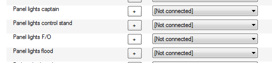
7. Now in Prosim configuration Tab I went to the Gates tab and “panel lights captain” I selected the specific pokeys card (I have only one card) and specified the port number “43”.
8. I also tried the “panel lights control stand” option but no luck.
Please advise if I have to do something else or where I am making a mistake.
Regards
Mouli
Hi Mouli.
I think I used the “Flood light” option in Prosim, but is should work nevertheless. In the Prosim configuration I think you can manually set the value to on/off.
The wiring sounds okay. However one thing comes to mind: The Pokeys card can not handle things that require a lot of power. That is why you need the LED Extension Board if you plan on using it as an outputs card. The Pokeys card it self simple can not supply that much power. That might be the case here as well.
One thing you could try is to supply the relay board with 5 v directly from the power source instead of via the Pokeys card.
I think I have relay connected to a Pokeys card at home. If that is the case I will check my wiring to night and post it here.
Thank you Peter. I will try the above and you please let me know once you check it out to night.
Wiring a relay with the Pokeys card:
5v power: 5v goes to VCC. GND to the pin labeld GND next to the jumper. The jumper sits on the left and middle pin.
Signal from Pokeys: signal goes on “IN1” and GND from Pokeys sits next to IN1
Dear Peter,
Thanks for the update and also for all the pains you take to guide me. Much appreciate you efforts.
I tried out the following.
Power:
1) 5V went to the relay board VCC near the JDVCC.
2) Ground went next to the VCC ground.
Signal:
1) From Pokeys port 11 went into the IN1 of the relay card
2) GND from the Pokeys went into GND next to the IN1
Light:
1) 12V went to the LED strip +side directly
2) Common From supply went into the relay board relay 1 Middle pin
3) From the NO I supplied the –ve of the Led Strip.
The good news is that when I switch the Ground power on and off on Prosim on off the relay red light goes on and off. This means the relay is working on and off but only the LED Strip light does not switch on and off. I know I am very close but some small mistake somewhere.
Note: port is assigned to the flood light on Prosim gate.
Any ideas?
Regards
Mouli
It sounds okay.
I would connect the GND/common directly in stead. But that is a matter of taste.
Have you tested the LED strip without the relay(just to narrow down the positive sources for the error)
Hi Peter. Thanks for the tip to control backlight. I have got more or less the same relaisboard. I have bought them on aliexpres in China for only €1.95 per board. It work’s perfectly. Many thanks. Greatings from the Netherlands
Hello Peter,
Nice to get in touch with you again. Hope you are doing well and i saw your post that you are moving to a new house. Good to you and the family.
Can i ask you if i can get the details for the landing light toggle switch attachment. looks cool and i would like to get it from them.
Let me know if this is possible.
regards
Mouli
Hi Mouli.
If you are referring to the big chunky landing light toggles that you put on the switch I have ordered mine at lynx.dk
Thank You Peter. Much appreciated for the prompt reply.
Hi Peter.
I bought the OC Dim Control and could never get it to work properly. I reached out to Claus Hansen and he told me about these cheap dimmers. I ordered 2 and got them working correctly for the backlighting. I pretty much took apart the casing and mounted them behind the captain light panel.