
Remake of the ADF
319. January 2014 by Peter
 I have made my ADF-radio in a new version last week.
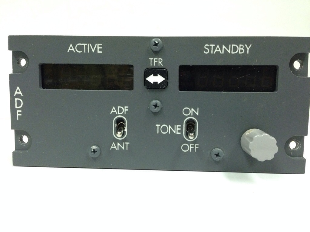
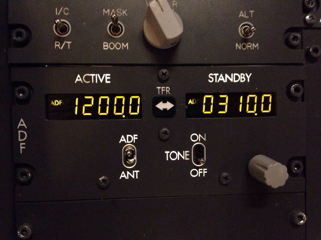
Up until now they have not worked mostly due to my SIOC script not working for some reason. But once I got SIOC working I noticed that the script allowed for the ADF/ANT indicators on my radio to be put in to use. So I decided to make a new version of my ADF-radio that included the AFD/ANT indicators next to the digits.
 I found some dark tinted foil on ebay last month and two layers of that film really made an improvement compared to the reflective sun film I have used up until now. You can see it on the picture above where it not is possible to se the 7-segment units.
So I better start remaking all my radios so they all use this dark film.

I also found out that in order to get the digit working the specific pin on the fourth 7-segment unit must be hard-wired to the master card. And furthermore you must cut the connecting lanes (Or whatever they are called) on the 7-segment PCB’s that I use. But it works fine now.
The radio is – as all other panels I have made – build in layers. I’ll post a video about it later. But you can clearly see here that there is a layer of plexiglass behind the panel.

This layer of plexiglas holds must switches and the LED-strips used for backlighting.
As you also might notice the panel is a mess in wired. There are 5 switches on the panel (3 switches + encoder + encoder-push). I normally make a backplate with all connectors on. Then it is easy to connect with dupont-cables.
For this panel I decided to also make connectors for the 7-segment displays. Normally I connect them directly from the PCB to the Display-card.
But sometimes this solution results in loose connections later down the road.

So with this middle station I hope to prevent this later on. As you might see from the picture the ADF/ANT-indicators require a resistor (330 ohm). But the decimal-points (The last two pins on the LED-row) should not have a resistor connected. It takes 5v.

Hey Peter !
I leave a reply here because if i could, il would comment on all your posts !
Thank you so much for sharing all the information with us 😀 I’ve been watching all of your videos and right now i’m getting through this entire blog 🙂 I always had the idea of building a cockpit in my mind (or should i say dreams…), but i have to say it’s because of you that i finally decided to get myself to work 😉 So the last few days i have started planing all of this big project following your guide. I’m almost finish with the plans, and as i’m writing this, i am designing it in a 3D software. I’m building this for my Royal Canadian Air Cadets squadron. The room i have been provided is really small so i have to cut the cockpit in half, meaning that the MIP will only include Captain’s instrument panel and Centre / engine instrument panel. And my budget is quite low so for now, i will stick with DIY stuff and dummies ^^
Anyways, i really look forward in this project and yours too ! I wish everything will go as you planned 🙂
Thank you again and…. fly safe 😉
Roy
[…] About halv a year ago I wrote about how I make panels. […]
This is an impressive build with some clever solutions for wiring and display integration.