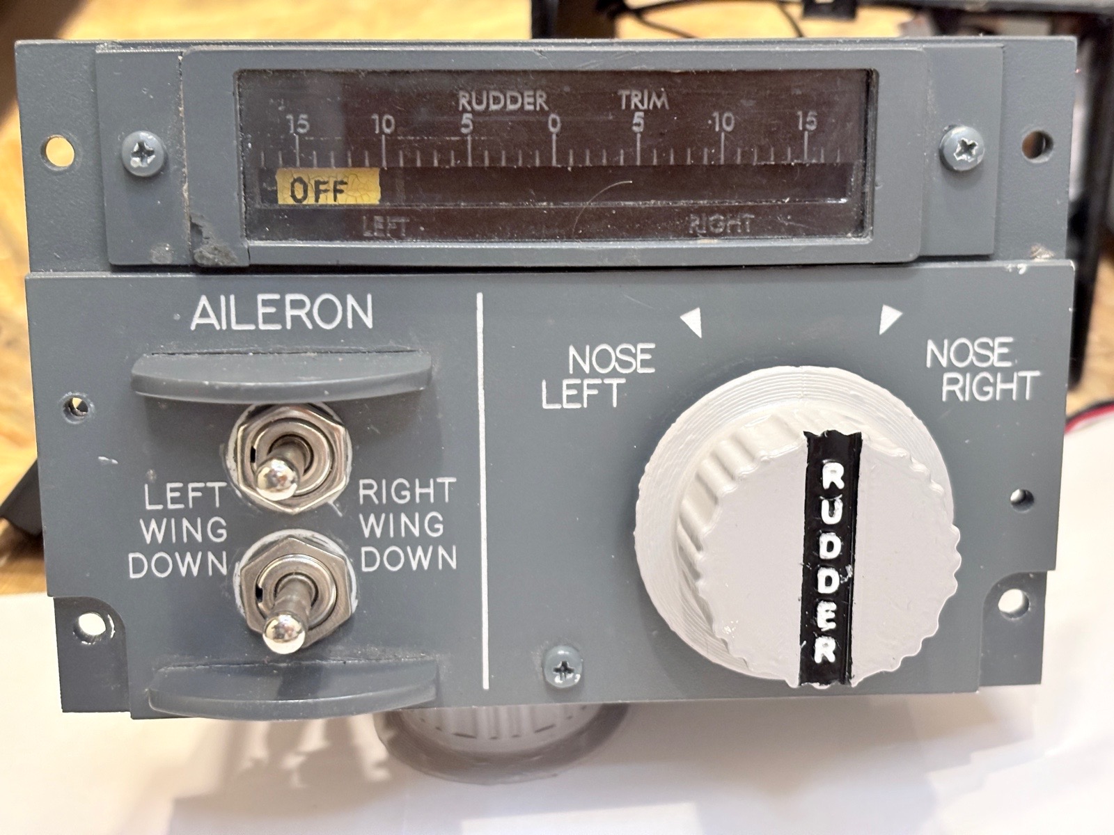
Rudder Trim & OEM
Leave a comment29. October 2025 by Peter
One panel that I never have used is the Rudder Trim at the back of the pedestal. But a few months ago I got my hand on an OEM Rudder Trim switch. So I better interface the panel.
The switch is spring loaded to center. So when released it returns to center. Each side (Right / Left) have two steps. And some interesting wiring.
Making the panel had three phases:
1) Wiring
2) The Trim indicator
3) Making a structure/case for the entire thing
I will short address those in this article but also recommend watching the video as a picture tells a thousand words.
Wiring
On the side of the switch there is a wiring diagram. So wiring this should be easy.
It has two NULL / GND inputs because there are two groups of switches. The first group is a left / right pin. So if you twist it to the right there is a signal on one pin and vice versa when you go left. This is strait forward. If you then twist the knob further the second group is activated. This is where things get a bit tricky. The second group only has one output pin. So no matter is you twist it all the way to the right or all the way to the left it is the same pin that sends a signal. This of course is combined with the left/right pin in group one.
Rudder Trim indicator
The rudder trim indicator I have made from a fully belt that is also used on 3d-printers. Easy peasy. The markings are hand drawn with a pen. We call them Posca Pen they can write of things like stones and black surfaces. One white and one yellow.
To move the pulley Belt I made a pulley wheel in Fusion 360. There is a in build function so it is very easy to make. I calculated that I needed 110 teeth on the wheel to the pulley belt go all the way from left to right with in the limitations of the servo (270 deg). Inset the variables in Fusion and after 10 seconds there is your customized pulley wheel.
As servo I have used a heavy duty servo with metal gears.
Structure
This took quite some time with designing in Fusion 360, printing a prototype, measure, redraw, print again.
I have made a small enclosure for the rudder trim indicator. It needs to hold two small pulley wheels and have some backlightning.
The OEM rudder trim switch is not a light piece. It requires quite some torque to be turned (Like all OEM stuff). It is mounted to the 3d-printed structure (Not the panel it self) So I had to insure that the stress/torque from turning the switch was evenly displaced on to the rest of the 3d printed structure to insure nothing the mount not snaps off.
As always I make an enclosure for the entire panel – Normally 8 cm deep. Because the OEM switch is so big I ended up with a 12 cm box this time.