
Inside a OEM Weather Radar Panel
Leave a comment14. January 2021 by Peter
I bought a real weather radar panel a few years ago and in the process of interfacing it I did a video on the inside of this panel that might be of interest to you.
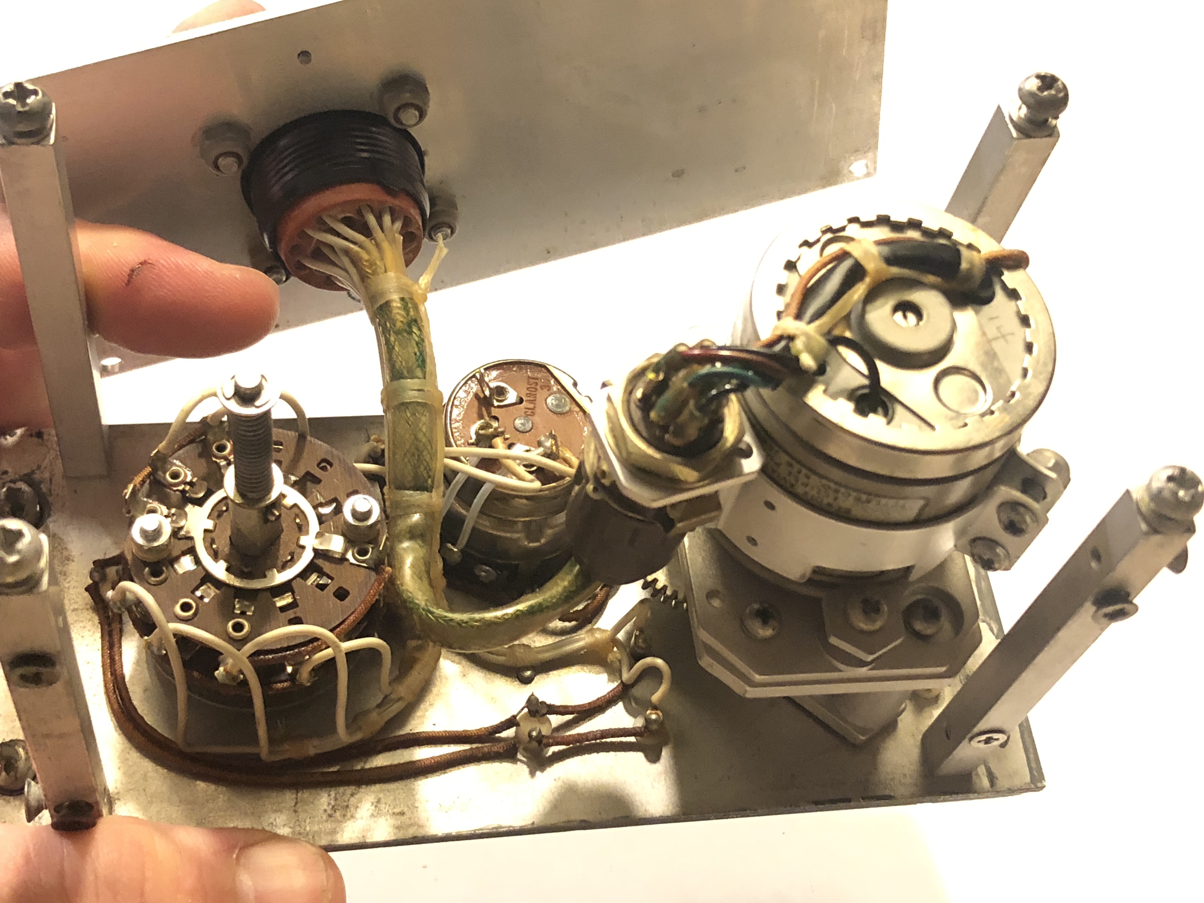
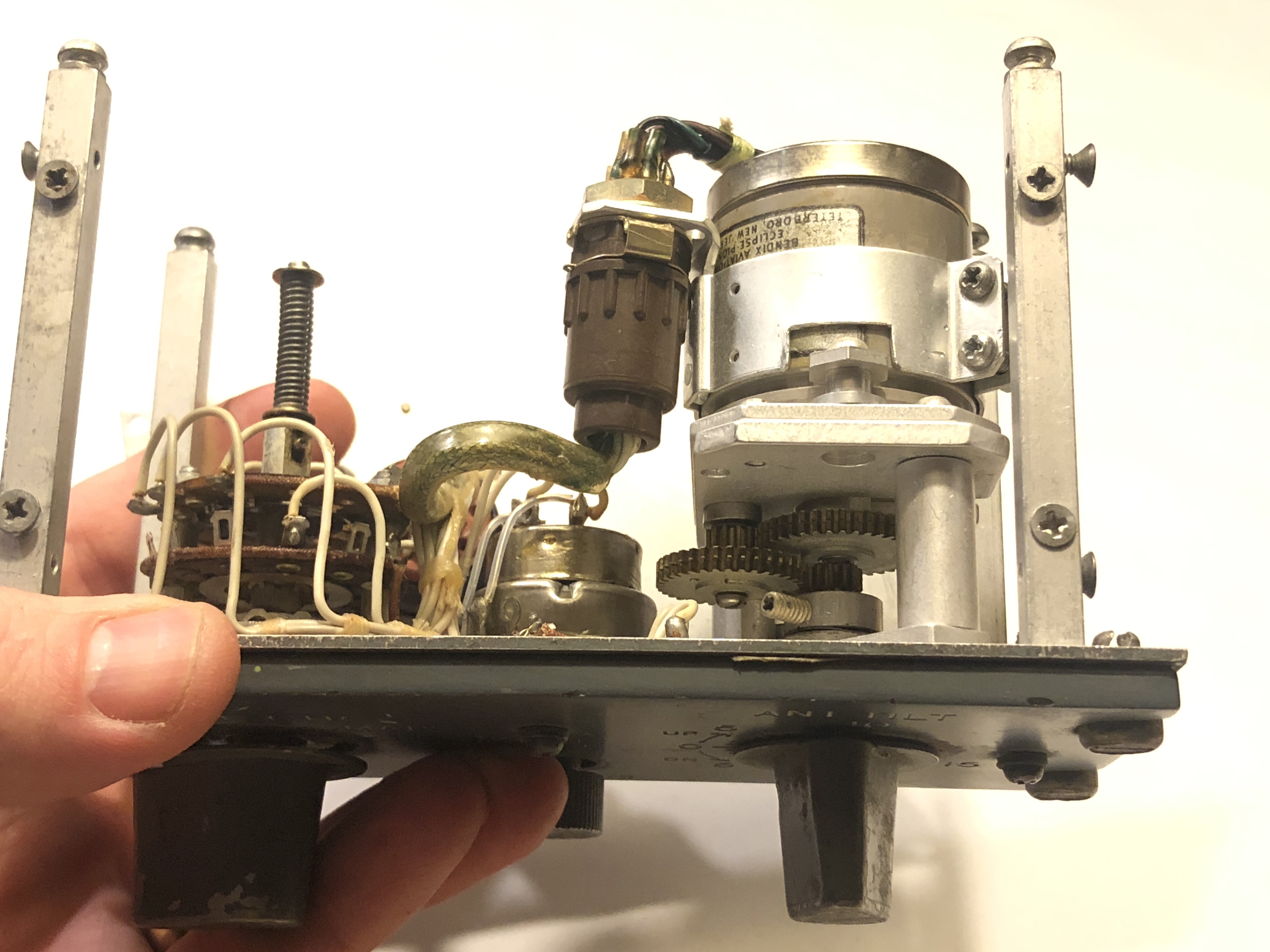
The panel consist of a switch, a potentiometer for the gain and a potentiometer for the radar tilt. The two first ones are pretty straightforward: there is a rotary switch with a “pull to turn” function for the TEST position. The GAIN is a potentiometer but it also has a switch for the AUTO-mode. The most interesting part was the Radar Tilt which turned out to contain stepper motor and not just at the expected potentiometer. I am unsure of the function of the stepper motor. As far as I know the aircraft is not able to turn that knob by it’s self. So I don’t see the need for the stepper motor.

Rotary switch to the left. Motor to the right 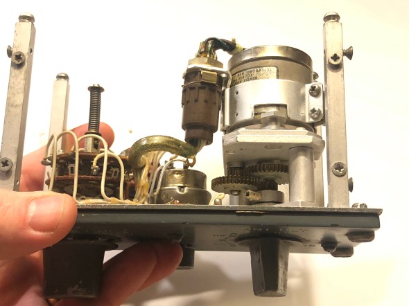
Note the wiring on the rotary switch (left). Stepper motor on the right.
Aviation electronics is a lot more complex than your regular simulator panels. A simulator panel just needs an on/off switch is to tell the computer the state of the switch. But in aviation panels there is actually logic going on inside the box. That can be electronics or different kind of wiring that sends signals in different directions. I had this experience with both my Audio Selector Panel and the weather radar that the wiring inside these boxes are designed for aircraft and simulators. So things quickly get very complex inside these panels.
On my two conversions ofAudio Selector Panel and the Weather Radar panel I’ve had my best success with just gutting the entire panel for all the wires and electronics and just start a rewire of the switches to my own connectors at the back of the panel.
I will post my progress on the conversion in about a weeks time.
