
Fire Handle Wiring Pinout
Leave a comment2. November 2024 by Peter
I have been lucky and got my hands on a set of OEM fire handles from a real Boeing 737.
Wiring these units seems pretty easy. There is a wiring diagram on the side. But still it caused a bit of frustration.
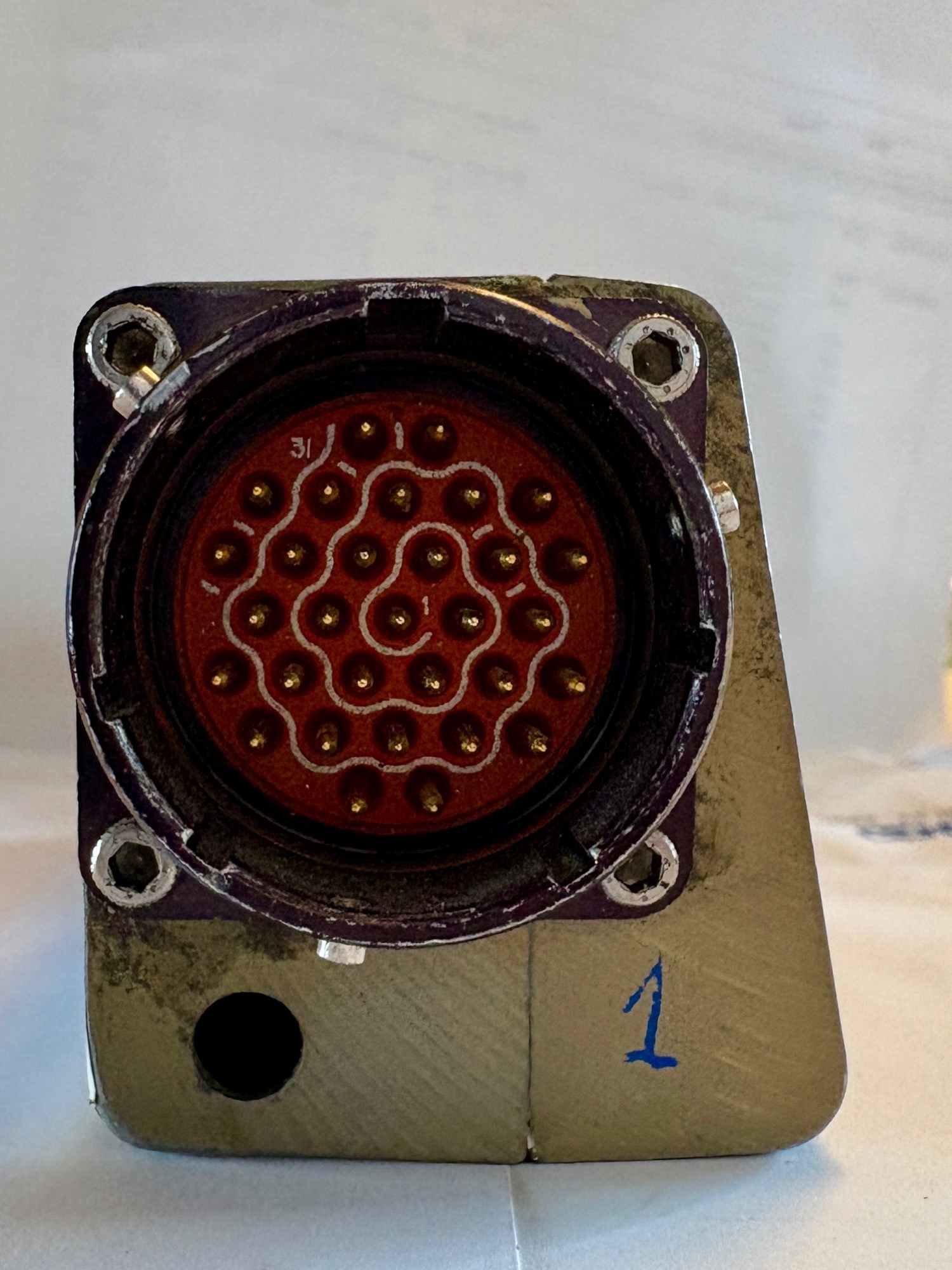
On the back of each handle there is a 31-pin cannon plug. PIN number 1 is in the middle and then it rotates clockwise outwards to pin 31. Pin 10, 20 and 30 is marked with a small white mark.
Finding corresponding cannon plugs can be a bit difficult. I found some female socket / male pins cannon plugs at around $200 each. Just a bit over the top when 3 is needed. So searching on Chinese shops like AliExpress I found similar plugs at $40 each. Again a total of $120 just for plugs. So I am sticking with just having the wires plugged in and hold together with zipties.
Interfacing ought to be pretty easy as there literally is a pin out diagram on the side of the handle.
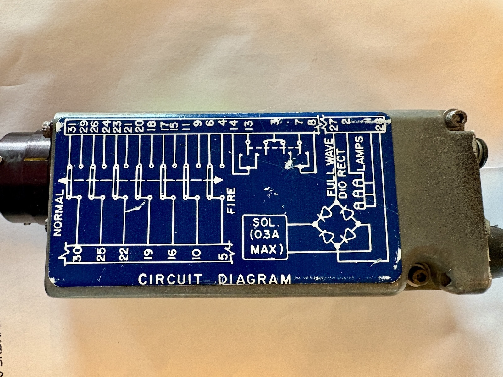
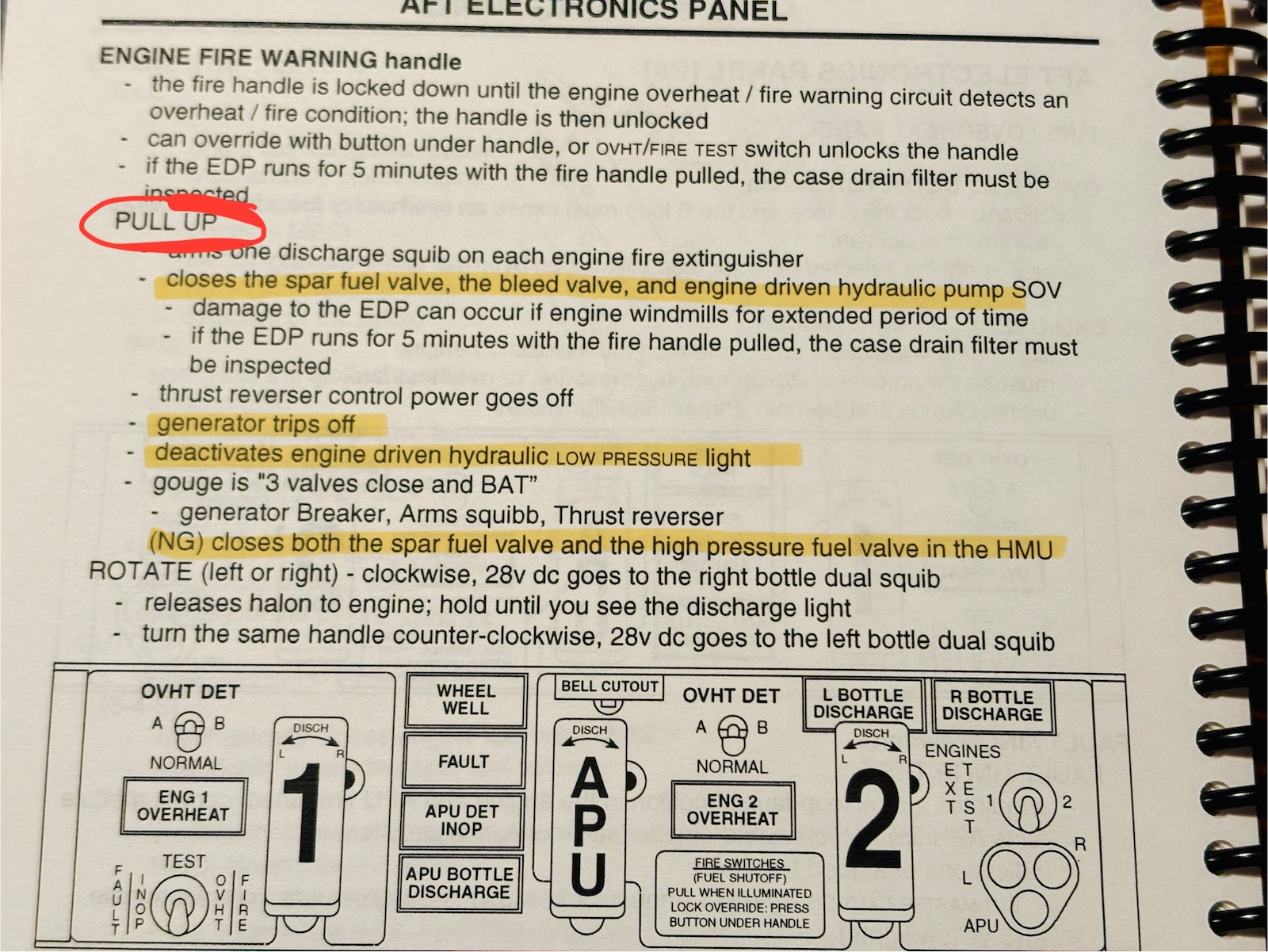
Most of the pins is used to tell different systems in the aircraft if the fire handle is pulled up or down. When the handle is pulled up different systems in the aircraft is bypassed. The way the Boeing 737 is wired if 7 systems is affected then 7 sets of wires are needed on each handle. The alternative would be some sort of signal-bus that would split/spread the signal through out the aircraft. This could lead to multiple points of failure which – I recon – is the reason it is wired directly from the fire handle to the individual systems – thous adding weight. This can be wired via pin 4 + 6 and pin 5 as ground.
Because there are systems being bypassed when the handle is pulled there is a solenoid inside the handle that locks the handle to prevent it from being pulled by mistake. When the solenoid is powered. by pin 27 + 28 it releases. Strait forward electronics.
The electronics inside the handle runs on 28 volts. A common aircraft voltage but not that common in home electronics. I solved this by getting a 24v power supply with a small screw for voltage adjustment and then cranked it up to 28v. The mentioned electronics inside is the solenoid and then 3 light bulbs in the handle. Because the solenoid needs 28v there is no reason to replace the light bulbs with – lets say – led strips. That would just add for an additional needed voltage. The 3 light bulb are easily lit up with pins 1 + 2.
Finally there is the turning of the handle. This is where I ran in to a bit of problems.
The handles – when pulled up – can be twisted to either the left side or the right side. It takes some force to turn it. So I had these handles laying on my desk while I was checking the pins with a multimeter. From the drawing on the side I could see that pin 3, 7, 8, 13, 14 had to do with the handle. But when turning the handle to either side I got absolutely no signal. No matter which combination I tried with my multimeter – nothing!
It took me more or less a day to figure this out.
See, the handles can be turned to the left or right. And as mentioned it does require quite some force and then it clicks to the side and the handle restes in the new position – lets call this 20 degrees to the side. At this position I got no signal at all on the pins. But actually the handle can be twisted just a bit further to each side like an additional 5 degrees. It is not a permanent position – as it the handle is spring loaded at this point and returns to the 20 degrees dent/stop mentioned before. When twisting (and holding) the handle to this 25 degree position I got a signal just as stated at the pin out diagram.
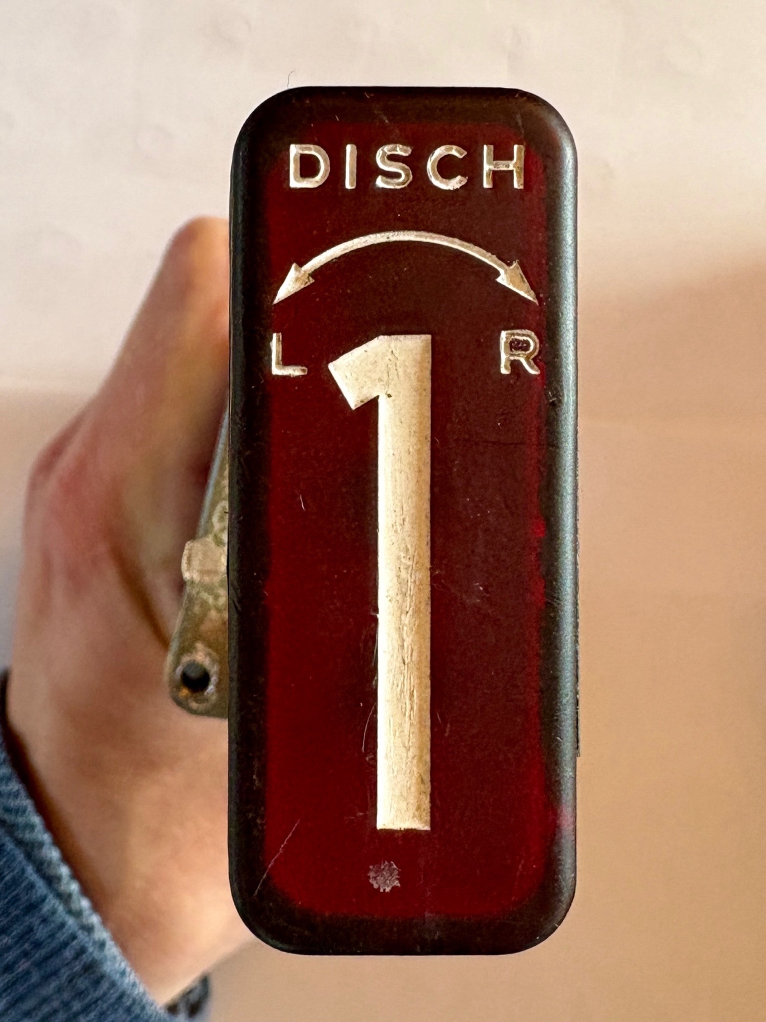
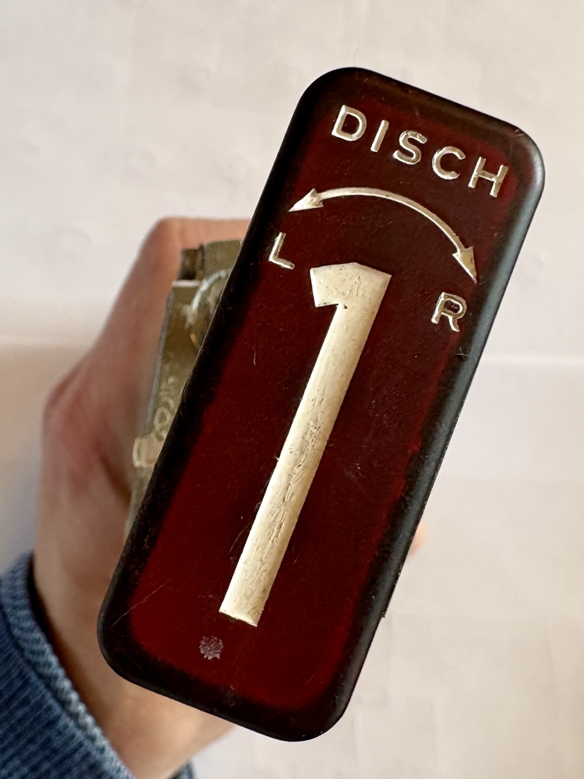
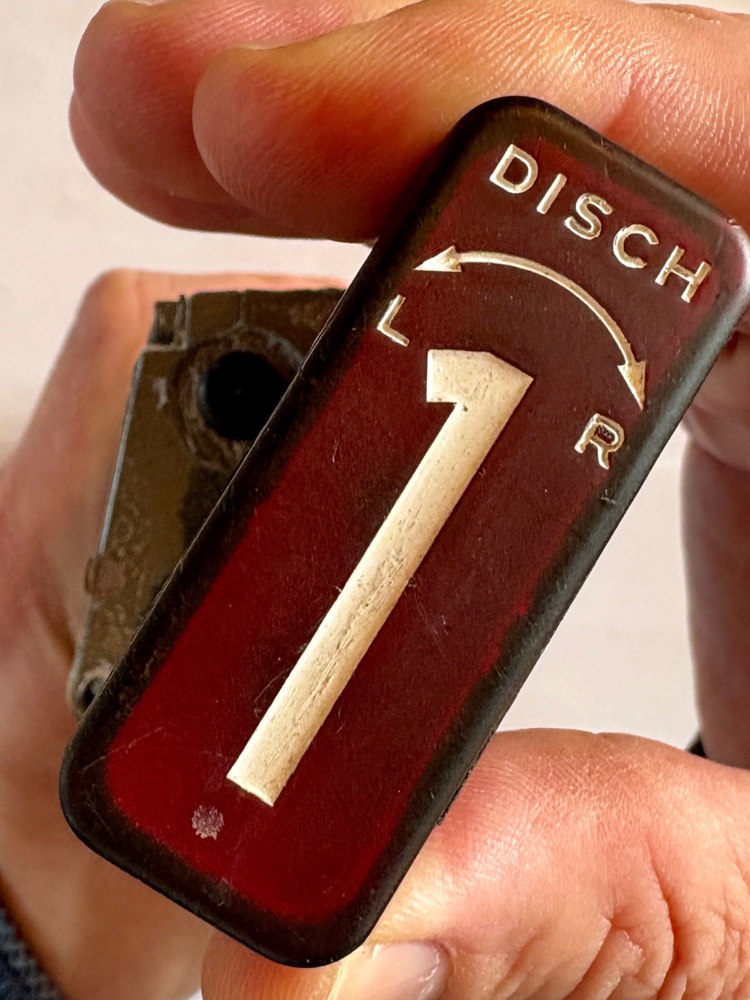
So the issue arose because I had the handle laying on my desk while my hands was busy using the multimeter. My hands should also be holding the handle at that extra +5 degree position. So just as the wiring diagram mentions pin 3 is ground. Pin 7+8 is one side and pin 13+14 is the other side.
